Current Sources Theory
This site provides an overview of current source theory, offering insights into improving current sources and
highlighting the key parameters of interest.
Theoretical current source
In these formulas, \(I_B\) represents the base current of the transistor, \(I_o\) is the current sourced by
the
circuit, and \(\beta\) denotes the low-frequency current gain (amplification factor).
$$ I_B = {V_{cc}-U_{BE} \over R_1}$$
$$ I_o = \beta * I_B$$
$$ I_o = {\beta * (V_{cc}-U_{BE}) \over R_1}$$
The issue with this type of source lies in the direct dependence of \(I_o\) on the supply voltage
(\(V_{cc}\)),
the base-emitter voltage (\(U_{BE}\)), and the amplification factor (\(\beta\)). Both \(U_{BE}\) and
\(\beta\) are
temperature-dependent: \(U_{BE}\) decreases approximately by 2 mV per degree Celsius, while \(\beta\)
increases with rising temperature. These variations cause an increase in \(I_o\), potentially leading to
thermal runaway. For this reason, such source is not recommended.
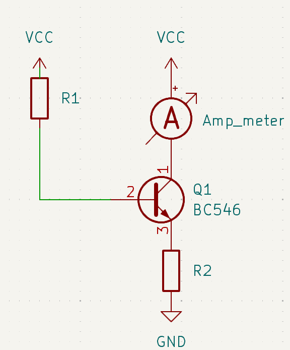
Simple current source
The simplest current source that can be constructed is a single-transistor source with a base and emitter
resistor.
The current \(I_o\) can be calculated using the following formulas:
$$ V_{cc}=U_{R1}+U_{BE}+U_{R2}$$
$$ U_{R1}=I_B*R_1 $$
$$ U_{R2}=I_{R2}*R_2 $$
$$ I_{R2} = I_o+I_B $$
$$ I_o = \beta * I_B$$
$$ I_o = {\beta * (V_{cc}-U_{BE}) \over R_1+R_2+R_2*\beta}$$
Again the issue with this type of source lies in the direct dependence of \(I_o\) on the supply voltage
(\(V_{cc}\)),
the base-emitter voltage (\(U_{BE}\)), and the amplification factor (\(\beta\)). Both \(U_{BE}\) and
\(\beta\) are
temperature-dependent: \(U_{BE}\) decreases approximately by 2 mV per degree Celsius, while \(\beta\)
increases with rising temperature.
These variations cause an increase in \(I_o\), which gets reduced by the Emitter resistor, as an increase in
\(I_o\) leads to a higher
voltage drop across the resistor. This increased loss does decrease the base current. If an emitter resistor
is choosen it's beneficial to use
one with a positive thermal resistance change. This is mandatory to cancel the thermal runaway and does
reduce the current at high operation temperatures.
Nevertheless such source is not recommended.
Voltage divider current source
To further minimize the transistor's dependence on the supply voltage, a voltage divider can be added as a
reference.
The sourced current Io can be calculated using the following formulas:
$$ V_{cc}=U_{R1}+U_{BE}+U_{R3}$$
$$ U_{R1}=(I_B+I_{R2})*R_1 $$
$$ U_{R2}=U_{R3}+U_{BE} $$
$$ U_{R3}=I_{R3}*R_3 $$
$$ I_{R3}=I_o+I_B $$
$$ I_{R2}={U_{R2} \over R_{2}}$$
$$ I_o = \beta * I_B$$
$$ I_o = {\beta * (V_{cc}*R_1-R_1*U_{BE}-R_2*U_{BE}) \over
R_1*R_2+R_1*R_3+R_1*R_3*\beta+R_2*R_3+R_2*R_3*\beta}$$
In these formulas, \(I_B\) represents the base current of the transistor, while \(I_o\) is the current
sourced by the circuit. \(\beta\) denotes the low-frequency amplification factor.
By incorporating a voltage divider as a reference, it is possible to further reduce the dependence on the
supply voltage.
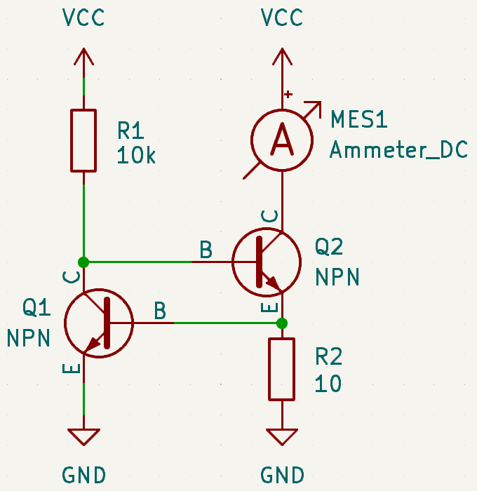
Dual Transistor current source
The use of a dual-transistor source offers two key benefits. First, it provides a source with a positive
temperature coefficient, which prevents thermal runaway. Second, it requires only a very low dropout voltage
above \(R_{2}\).
The source current can be calculated using the following formulas:
$$ V_{cc}=U_{R1}+U_{BE1}+U_{R2}$$
$$ 0 = -U_{BE2}+U_{R2} $$
$$ U_{R1}=I_{R1}*R_1 $$
$$ U_{R2}=I_{R2}*R_2 $$
$$ 0=I_{R1}-I_{B2}-I_{C1} $$
$$ I_o=I_o+I_{BE2}-I_{BE1}-I_{R2}$$
$$ I_o = \beta_2 * I_{B2}$$
$$ I_{C1} = \beta_1 * I_{B1}$$
$$ I_o = {\beta_2 * (V_{cc}-U_{BE1}-U_{BE2}+{R1*\beta_1*U_{BE2} \over R_2}) \over
R_1+R_1*\beta_1+R_1*\beta_1*\beta_2}$$
Incorporating the two transistors as switching devices worsens the temperature behavior, as the current
decreases rapidly with rising temperature. While this results in a stable source, it is not very accurate.
Thermal compensated Sources
To significantly enhance the thermal stability of the sources, it is essential to address the issue at its
core: the
thermal dependence of the base-emitter \(BE\) diode and, consequently, the base current (\(I_b\)). This
dependence can be mitigated by continuously adjusting the
supplied base-emitter voltage (\(U_{BE}\)) to match the
transistor's own base-emitter voltage characteristics.
This adjustment can be achieved by creating a thermal drift in the supply voltage that mirrors the thermal
drift of
the transistor. There are various methods to accomplish this, and two straightforward examples will be
discussed
here.
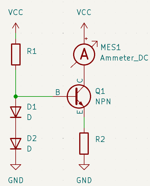
Diode compensated current source
To create a temperature-compensated source, it is essential to generate a base voltage that matches the
temperature characteristics of the transistor. This can be approximated by using a diode.
The current for this source can be calculated using the following formulas:
$$ V_{cc}=U_{R1}+U_{D1}+U_{D2}$$
$$ V_{cc}=U_{R1}+U_{BE}+U_{R2} $$
$$ U_{R2}=I_{R2}*R_2 $$
$$ I_{R2} = I_B+I_o$$
$$ I_o = \beta * I_{B}$$
$$ I_o = {\beta*(U_{D1}+U_{D2}-U_{BE}) \over R_2+R_2*\beta}$$
If standard silicon diodes are used, two are required to achieve a base voltage higher than that of the
transistor. Unfortunately, this eliminates thermal compensation because the thermal variations of the two
diodes combine and overcompensate for the transistor.
To address this, a single high-dropout diode, such as a LED, is recommended. Alternatively, a Zener diode
can also be used.
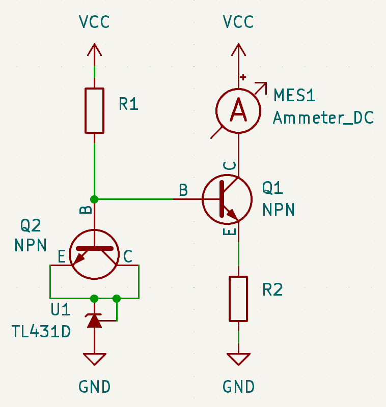
For a higher degree of thermal compensation, it is beneficial to use a transistor of the same type as the
one being compensated, configured to function as a diode. The offset level can then be established using a
precision reference.