Current Sources Simulations
This section offers an overview of current source simulations, providing valuable
insights into improving current source designs and highlighting the key parameters of interest.
For a deeper understanding of the simulated current sources, it is recommended to review the
current source theory.
The circuit used for simulation is illustrated on the right side of the page.
All simulations were performed in LTSpice, including temperature analysis using the STEP TEMP 20 100 macro,
which evaluates the behavior of the sources across a temperature range from 20°C to 100°C.
The BC817-40 integrated transistor model was chosen, as it closely resembles the BC817 transistor used in
the
measurement setup.
Notable information and deviations in the simulation setup include:
- Since LTSpice does not offer a native model for the TL431 shunt regulator,
the built-in LT1009 shunt regulator was used as a substitute.
- The resistors were selected to match those used in the measured current
source circuits to ensure comparable results.
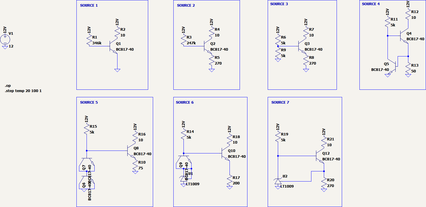
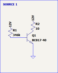
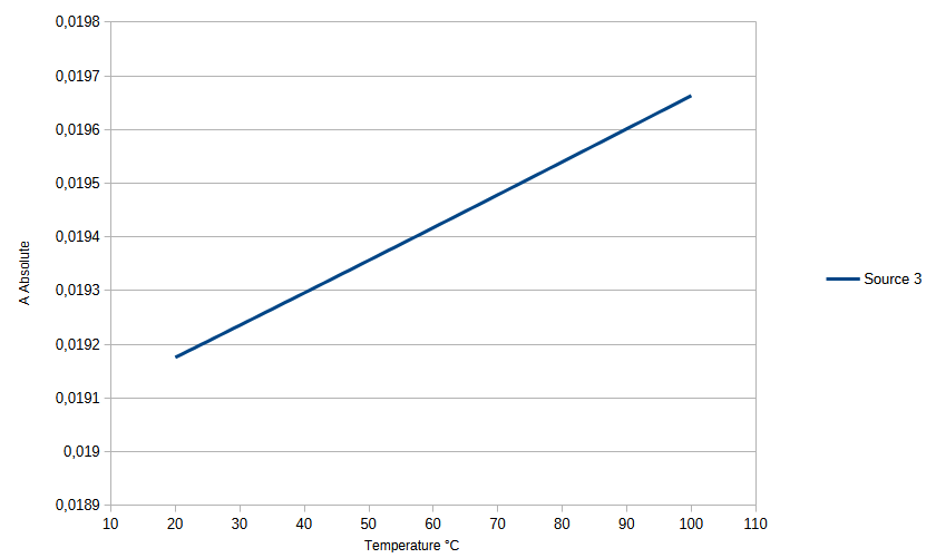
Simple Current Source
The simple current source consists of two resistors (without any temperature dependence) and a BC817-40
transistor.
The resistor values are matched to those used in the measurement setup. Since the transistor is not
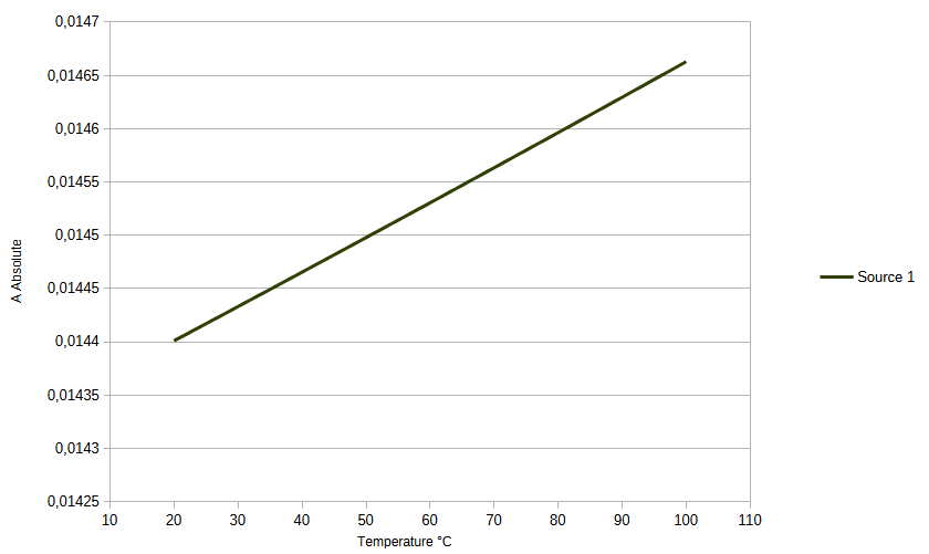
thermally stabilized, a strong dependence of the output current on temperature is expected.
Specifically, as the temperature increases, the base-emitter voltage typically decreases. This causes an
increase in base current, which in turn leads to a higher output current.
This behavior is clearly illustrated in the attached figure.
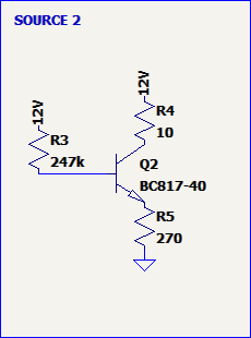
Emitter Resistor Current Source
The emitter resistor current source consists of three resistors (without any temperature compensation) and a
BC817-40 transistor.
The resistor values are aligned with those used in the measurement setup. Although the transistor is not
thermally stabilized and a noticeable temperature dependence of the output current is expected, the emitter
resistor provides a degree of compensation.
As a result, the temperature dependence is reduced compared to a design without an emitter resistor.
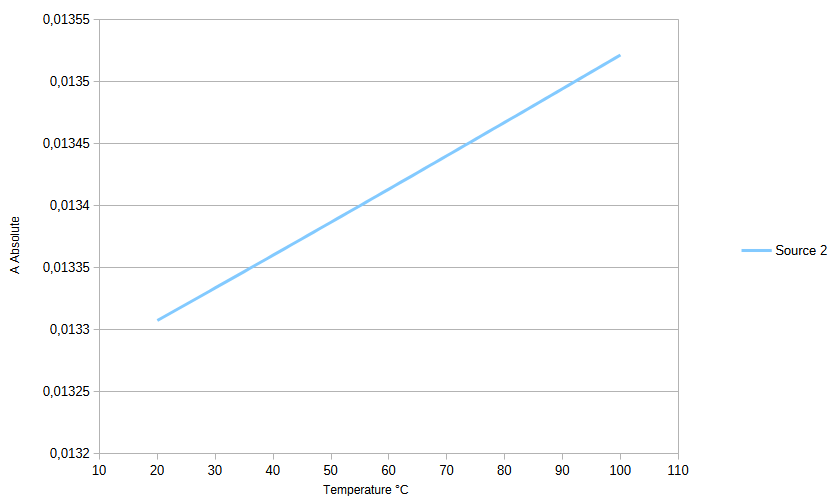
Specifically, as the temperature increases, the base-emitter voltage typically decreases, which increases
the base current. This effect is partially counteracted by a larger voltage drop across the emitter
resistor.
However, this compensation is not complete, and the output current still increases with temperature.
This behavior is clearly demonstrated in the attached figure.
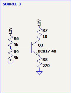
Voltage Divider Current Source
The voltage divider current source consists of four resistors (without any built-in temperature
compensation) and a BC817-40 transistor.
The voltage divider at the transistor's base significantly reduces the dependence on the supply voltage.
Moreover, if thermally matched resistors are used, the circuit's thermal stability can be further improved.
The resistor values are identical to those used in the measurement setup. Although the transistor itself is
not thermally stabilized, leading to some temperature dependence the inclusion of an emitter resistor helps
mitigate this effect.
Compared to a design without an emitter resistor, the temperature dependence is noticeably reduced.
As temperature increases, the base-emitter voltage naturally decreases, causing an increase in base current.
This rise in base current is partially offset by a corresponding increase in voltage drop across the emitter
resistor.
Nevertheless, this compensation is incomplete, and the output current continues to rise with temperature.
This behavior is clearly illustrated in the attached figure.
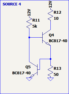
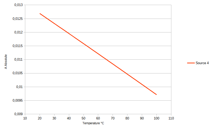
Dual Transistor Current Source
The dual-transistor current source is composed of two BC817-40 transistors and three resistors.
The thermal behavior of this circuit is primarily influenced by the lower transistor (Q5). As the
temperature increases, the base-emitter voltage of Q5 decreases, which in turn reduces the base current
supplied to the upper transistor.
This design inherently features a negative thermal coefficient, making it resistant to thermal runaway and
contributing to improved stability under varying temperature conditions.
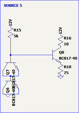
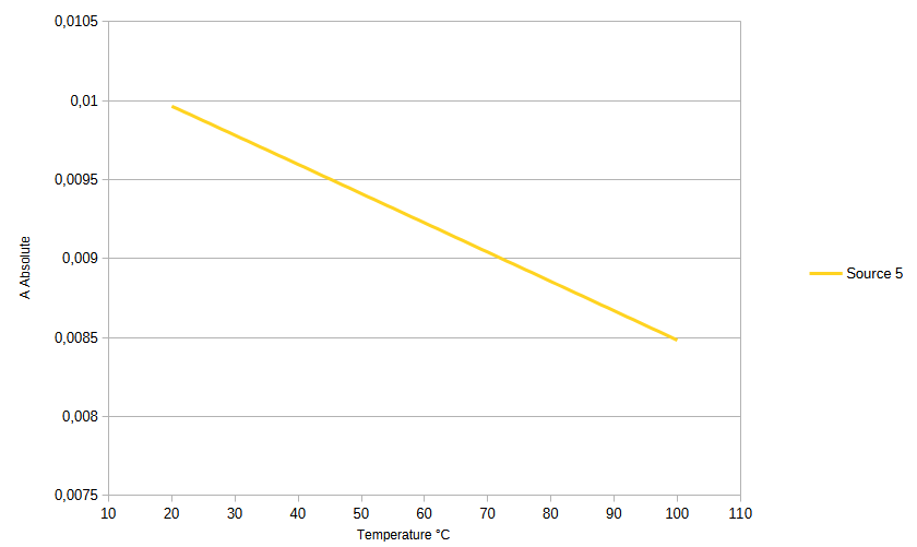
Diode Compensated Current Source
The diode compensated current source consists of three BC817-40 transistors and three resistors.
The thermal behavior is mainly governed by the interaction between the transistors. In this configuration,
transistors Q7 and Q6 are used as diodes and slightly overcompensate for the temperature dependence of the
main transistor Q8.
As a result, the circuit exhibits a slight negative temperature coefficient, enhancing its resistance to
thermal runaway and improving overall stability across temperature variations.
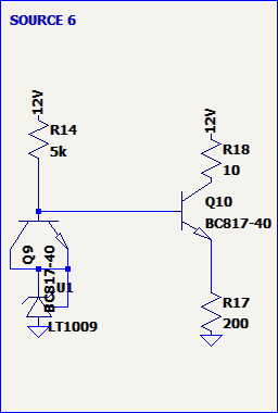
Diode Compensated corrected Current Source
The diode-compensated corrected current source consists of two BC817-40 transistors, three resistors, and a
temperature-compensated Zener diode.
The thermal behavior is primarily determined by the interplay between the transistors and the Zener diode.
In this design, transistors Q9 and Q10 are configured to precisely cancel out the temperature dependence of
the circuit.
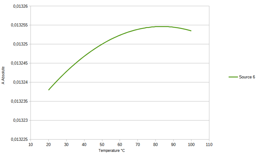
As a result, only the minimal temperature drift of the precision Zener remains, allowing the circuit to
achieve an almost zero temperature coefficient. The given curve does actually match the one shown in teh
datasheet of a lt1009 reference.
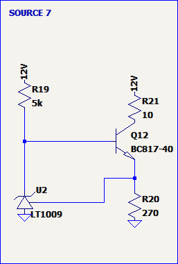
Diode corrected Current Source
The diode-corrected current source consists of one BC817-40 transistor, three resistors, and a
temperature-compensated Zener diode.
The thermal behavior is primarily governed by the interaction between the transistor and the Zener diode. In
this configuration, the Zener diode plays the key role in regulating the current.
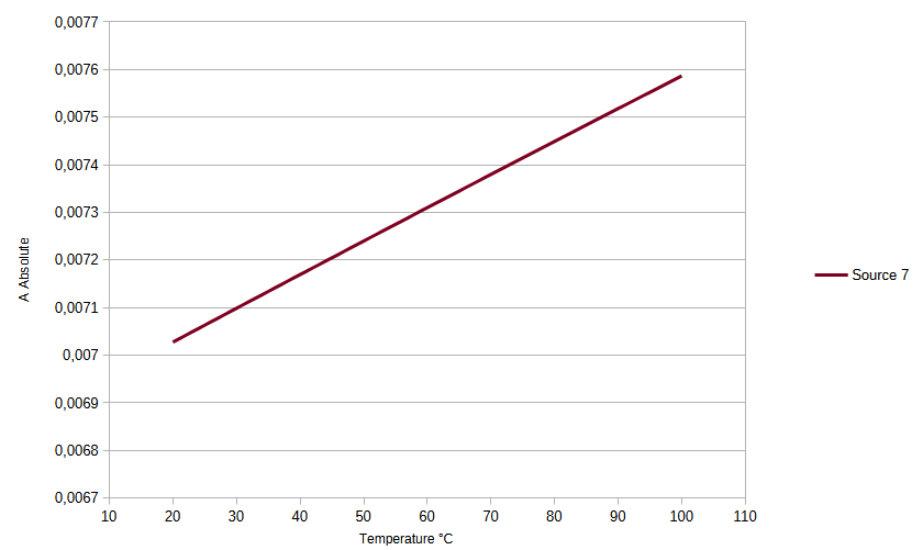
As a result, the circuit's temperature stability is mainly influenced by the Zener's minimal thermal drift.
When a high-quality, precision Zener is used, the overall temperature coefficient can be reduced to near
zero.
This design approach enables extremely low drift and high thermal stability.
Conclusio
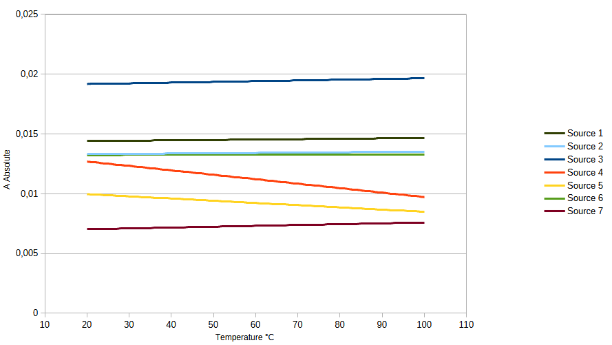
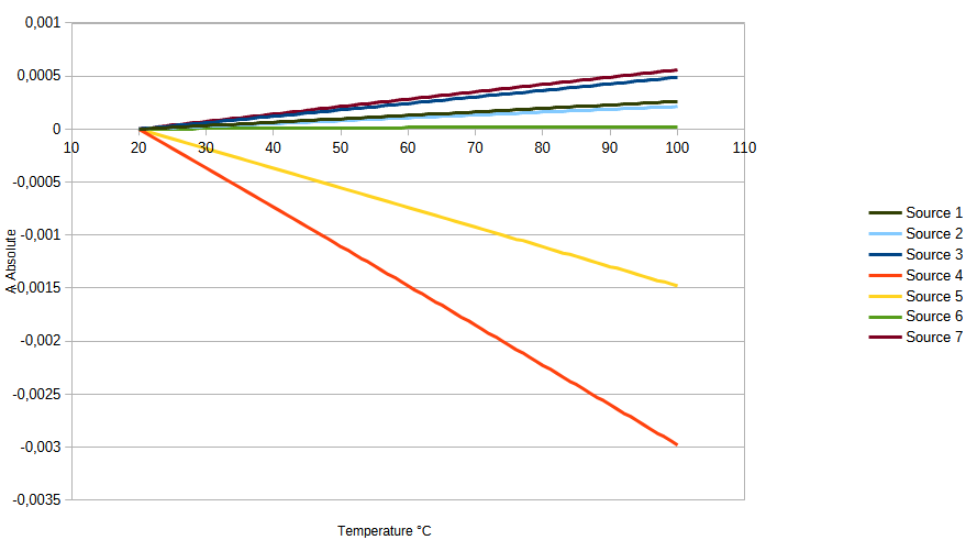
In conclusion, to ensure stable operation across a wide temperature range, it is advantageous to either
design a current source with a negative temperature coefficient or to thermally compensate the circuit.
The final simulation results—both absolute and relative values—are presented in the following graphs.